Introduction
Ethernet based bus solutions have become the dominant method of communications in motion and industrial control. TCP, UDP, Modbus TCP and EtherCAT are just a few of the Ethernet protocols implemented to bring high speed, robust communications to motion control applications. Since EtherCAT and Ethernet use the same physical hardware and are often used in concert, it can be difficult to differentiate between the two. Control systems designers can however make educated choices about the appropriate communication bus for their application by understanding just a few key factors; centralized vs. distributed control, determinism, and cost.
First, a brief overview of the two communication protocols will be provided. Centralized vs. distributed control and the role of determinism in motion control will then be discussed. Finally, the relative costs and advantages of each protocol will be outlined. The general rule is that EtherCAT is an appropriate solution for applications that require real-time, deterministic control over distributed networks. This capability is offset by the higher cost of EtherCAT hardware vs. conventional hardware.
Ethernet Communication
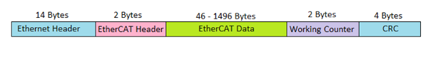
The primary goals of Ethernet communication are data integrity and throughput. Data is quantized into objects known as packets. Each packet contains a collection of fields such as source address, destination address, payload data etc. The data contained with the payload, labeled 'Ethernet Data' in Figure 1, can be any number of protocols. Galil Motion Controllers for example use the Telnet protocol to send ASCII data between the controller and host PC over TCP/UDP. 100 Mbit/sec speeds make this communication effectively instantaneous.
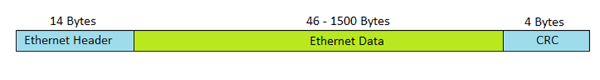
The 'effectively' qualifier is used because Ethernet communication does come with some overhead which may cause intermittent delays if, for some reason, a packet is lost or a collision occurs. Keeping all components on a closed network can minimize the chances of occasional delays, but they can not be completely eliminated. If it occurs, this delay is rarely longer than a millisecond and for the purposes of most motion control applications is a non-issue. This being said, Ethernet communications are often referred to as 'non-deterministic' since there is no absolute guarantee that information will arrive at the prescribed destination at a defined time.
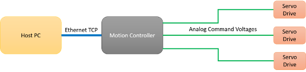
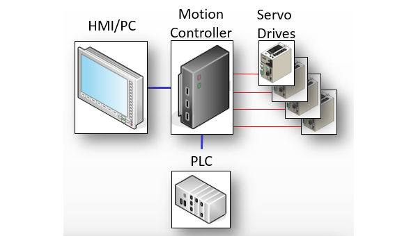
A block diagram of a motion control system that uses Ethernet to communicate with a host PC is shown in Figure 2. Notice that Ethernet communication is restricted to communication with the host and that communication with the servo drives uses the standard +/- 10V analog servo command signals. Real-time motion profiling, IO control and PID filtering are left to the motion controller. Since TTL level and analog voltages are transmitted across copper wires and PCB traces, communication between the motion controller and drives is negligible for even the most demanding applications. Non-real-time tasks are left to the host PC via Ethernet.
EtherCAT Communication
An EtherCAT solution still uses Ethernet communications between the Host PC and EtherCAT Master for non-time-critical tasks. Motion profiling and IO control is handled in the EtherCAT Master, similar to the system outlined in the previous section. However, the primary difference between the two systems is the method by which motion commands are relayed to the Servo Drives (referred to as EtherCAT Slaves in Figure 3).
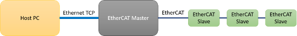
Instead of an analog voltage, 32-bit position commands or 16-bit torque commands are sent to each drive via the EtherCAT protocol. Data is transmitted in a packet structure similar to that used in Ethernet communications, see Figure 4. Similarly, encoder and IO data is returned to the EtherCAT Master. This all occurs at a regular interval known as the EtherCAT Cycle Time, typically in the millisecond range.
If EtherCAT uses the same packet structure as Ethernet, how does it get around the potential for communications delays? The difference is the high degree to which EtherCAT communication is coordinated and structured and the fact that no two EtherCAT transmitters share the same physical wire, eliminating the possibility of collisions. Each drive is equipped with an ASIC that allows it to take information directly from the EtherCAT packet and map it to its memory space while inserting information into the same packet. This data is then used to either profile motion or update position registers, depending on the mode of operation of the EtherCAT network. It is this direct mapping that makes for minimal communication delay and overhead. This allows EtherCAT network commands to be process at a speed that is on par with traditional analog based systems.
The high degree of coordination on an EtherCAT network does come at a cost. The network must be set up via software prior to use. Each EtherCAT Slave must be configured to 'look at' only a particular set of bytes within the EtherCAT packet, forwarding along data meant for subsequent drives on the network. An EtherCAT network is by necessity a closed network, incompatible with standard Ethernet hubs or switches. Lastly, since each EtherCAT slave must come equipped with the EtherCAT ASIC, digital/analog IO, servo amplifier and motion profiler, there is a significant cost increase over standard analog command drives. For select applications however, the increased cost is justified.
Centralized vs. Distributed Control
A centralized control system consists of an, aptly named, centrally located motion controller. The motion controller is responsible for motion coordination, IO scheduling and communication with a Host PC or HMI. A perfect example is a CNC machine, see the simplified block diagram in Figure 5. There is at least four axes of servo control and numerous IO points like limit switches, touch probes etc. in addition to a PLC for additional IO control. All input data and output commands are routed through a single device that can coordinate actions to within microseconds. In these systems, a clock based servo interrupt ensures that feedback is sampled and commands are written in a real-time, deterministic manner. Communication latency is minimal since all connections are copper based i.e. all on the same PCB or hard wired into other components. For increased speed, noise immunity, and reduced cost, drives that are integrated into the controller are the perfect option.
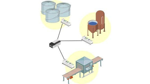
Factory process management that does not require tight coordination between actions is ideal for distributed control. In this scheme, shown in Figure 6, motion controllers and PLCs all share information over a communication bus, typically some form of Ethernet communication. Deterministic control of IO and motion is handled locally at each 'node' while a central master issues commands and monitors the status of the various devices. The benefit is that everything can be controlled from one location despite each node being physically separated by even hundreds of meters. The trade off is that each node must, in addition to monitoring and running its assigned tasks, handle communications as well. A closed network means that communication over Ethernet remains fast and reliable but as previously stated, there is no guarantee of precise timing.
Determinism
Using a defined hardware interrupt signal or EtherCAT cycle time synchronization pulse to ensure data is transmitted and acted upon in real-time are both examples of deterministic operation. Often the assumption is made that since EtherCAT is a deterministic network, it must be used in order to ensure this kind of performance. To be clear, in each case it is the motion controller or EtherCAT Master that is setting the pace. Deterministic performance is guaranteed in either case. In any system design, the crucial deciding factor between using a centralized motion controller or distributed EtherCAT network is the need for deterministic performance over long distances. Classic examples are a factory floor or processing plant. In layman's terms, EtherCAT is a means for sharing the servo interrupt between all devices on the network and doing so over the Ethernet bus.
In a broader sense, a perfectly deterministic system exists only in theory. In practice, determinism is a relative term. Electronic devices are slaves to the processor clock and transistor propagation times, typically measured in nanoseconds. These times define the upper bounds of how fast an electronic system can operate. However, most motion control systems can be perfectly controlled using a servo update rate in the kHz range. When the time resolution of a system is 1 ms, a handful of nanoseconds is for all intents and purposes instantaneous. Similarly, Ethernet communication, even with potential for occasional communications delays, is 'virtually' deterministic. The communication time between Host and Motion Controller is insignificant when compared to the requirements of the mechanical system.
Summary
Due to lower cost, simplicity of operation and decades of proven performance, analog control signals will continue to be the industry standard for some time to come. It is an established technology using standard components most engineers are familiar with. These control systems fit the bill for applications that allow for the controller, drives, IO modules and motors to be in close proximity or 'in the same box.'
EtherCAT is emerging as a solution to a very specific problem; real-time, deterministic control over long distances. The main disadvantage is cost. Every node on the line (drives and IO) must have the EtherCAT ASIC on board in order to properly read and write data. In addition, every drive must also implement what essentially is a motion controller that can generate motion profiles and handle PID control. This vastly increases costs over a standard analog command control system.
The goal then for a system designer is to accurately identify the goals of an application in order to assess whether the added cost and complexity of an EtherCAT control system is appropriate. Table 1 lists a few key decision points to consider when deciding between Ethernet and EtherCAT communications.
|
Ethernet |
EtherCAT |
|
Lower cost |
Higher cost |
|
Established Technology |
New Technology |
|
Virtually Deterministic |
Simplified Wiring over long distances |
Galil Motion Control has offered high performance motion controllers for over three decades and was a pioneer in the introduction of Ethernet communications to the motion control industry. Galil's flagship product, the DMC-40x0 series, is capable of handling the most demanding motion control applications using Ethernet communications with both internal and external servo drives.
In addition, Galil now offers a line of EtherCAT products for integration into new or existing applications that can benefit from the use of EtherCAT. The DMC-500x0 is also fully compatible with Galil's line of internal amplifiers. The DMC-52xx0 is an EtherCAT only master, capable of controlling up to 32 EtherCAT servo drives as well as 2 EtherCAT IO modules on the same network. In addition the RIO-574x0 is a dedicated EtherCAT IO module. Galil's line up of Ethernet and EtherCAT capable motion controllers ensures that we can meet the needs of your application, regardless of the requirements.